This is a project I've been planning for many years. It's a design for a fully mechanical universal Turing machine. My self-imposed constraints are to use no electronic or even electrical components, to be driven by a single rotating input shaft, and to be constructable with simple hand tools, without relying on high precision parts.
Trying to design something like this is an interesting challenge, and something I've found I can work on entirely in my head when I'm stuck somewhere with some spare time and not even as much as a sheet of paper to draw ideas on. Some of you might like to stop reading here and try and figure out a design yourselves before this plan taints you.
I had most of the conceptual design finished at the start of this year, and it's taken until now to get a fully specified model made up in OpenSCAD. I think this is now ready to manufacture.
One of the most difficult initial problems is how to store a reasonable amount of data, such as the tape for a Turing machine without having to manufacture a large number of custom parts. My design uses ball bearings on a sheet of pattern perforated metal as the tape. The position of balls on the grid is the data, and the machine moves back and forward on the grid. To be strictly universal, the perforated metal sheet needs to be infinitely long. I haven't carefully examined the sheet RS have sent me but will assume it to be infinite for the time being.
I'll now try to describe how the rest of the machine works, which is pretty difficult and I don't think this will be immediately clear. I hope to have a working prototype soon which should make its operation clearer.
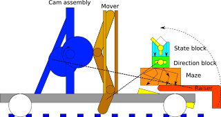
 This schematic diagram shows the main components of the machine.
The next component after the grid and set of ball bearings is a lifting arm or raiser (red) which picks up the 'input symbol' under the read head and lifts it to the top of a block of channels not unlike a marble alley. The run needs to contain some state which will direct the ball down different channels, and needs levers which will update the state for the next ball, and set the direction the machine will move. It also needs to direct the ball back to a new position on the perforated sheet to 'write' the new symbol.
First in the run is the 'state box' (cyan) which diverts the ball down down one of two paths depending on the position of the gate. The position of the gate is the state of the Turing machine. Paddles on the gate also turn the gate as the ball falls, setting the new state of the machine. The output of this box is a ball in one of ten positions, representing the combinations of five input symbols and two initial states.
The next part is the 'direction box' (green) which has levers in some of the ten paths which will alter the direction of the Turing machine later on. If a lever is hit, the machine moves left, and if not, it moves right. The actual movement isn't carried out in this phase, as the falling ball won't have nearly enough power to move the whole machine, but it sets state which will be picked up later.
After falling through the state box, the ball falls into the 'maze' (orange) which maps the ten input positions into one of five output positions, which is the output symbol for the machine. A set of gutters under the maze will return the ball to the grid in its new output symbol position.
Behind the marble alley, there's a tower which performs the movement for the whole machine. A cam (blue) drives a set of three levers (brown) which move the machine. The bottom lever can be easily deflected from one side to the other while it's raised; this is done by a linkage from the direction box. The cam drives the levers downwards, where they engage with the grid and push the whole machine forward or backward two grid spaces.
There are other cams to run the raiser and to reset the direction box each cycle.
The whole machine rides on wheels which ride on top of the grid. Using round wheels on a square grid will provide a small amount of alignment so the machine doesn't drift away from the positions of the balls.
This machine is a 5-symbol, 2-state Turing machine. The configuration comes from Stephen Wolfram's "A New Kind Of Science", which shows this to be a universal machine. While it's relatively simple, it's also ridiculously inefficient and could not be used as a practical computing device. It's just meant as a demonstration of how simple a universal computer could be.


