No longer updated!

My blogspot site is no longer updated. Most of the posts here are archived at www.srimech.com along with new content.

Friday 2 November 2012

Error correction of the NPL time signal

There's a project on the back burner at London Hackspace to make a better alarm clock. One of the first things we need for this is a way to figure out the current time, instead of bothering the user to set it.

There are a number of ways to obtain this automatically. Both GPS and GSM could be used, and in most houses, WiFi could be used to connect to a time server. DAB is also a possibility in Europe. None of these are particularly cheap though. It would be difficult to get a receiver working for under 20 pounds with any of these methods.

The National Physical Laboratory transmits a time signal by low frequency radio from Cumbria. This is also known as MSF from its old radio call sign. Similar services exist in Germany and the USA, at least. A receiver can be had for 9 pounds from PV Electronics, however, using it hasn't been particularly easy. The signal coming from the module is TTL level, but in my experience, very noisy in the time domain. The signal I got on the first try looked more like this:


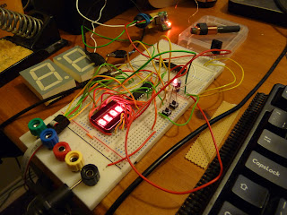
Eurgh. Some of this is due to the power supply; the module needs a very clean power supply and it took me a long time to get any sensible data while running from a mains supply. Giving the Symtrik module its own linear regulator, some big capacitors and a choke seem to have improved it. The orientation and position of the antenna is also important; I've noticed that it will produce garbage if it's too close even to an AVR running at 1MHz. LCD monitors in particular seem to drive it crazy.

We could use analogue means to try and get an average value over the expected length of a pulse, or sample it several times and take the most common value. Those are approaches I might go back to, but for now, I'm sampling it just once in the middle of the pulse.

The MSF Specification is pleasantly simple. The most important thing to recognise is the minute marker, since all the remaining data frames' meaning is dependent on their sequence after it. If you treat all the frames as 4-bit frames, sampled at 150, 250, 350 and 450ms from the first rising edge, then the minute frame is all 1s, while the other frames always look like XX00. By using four samples it's unlikely to detect a false minute marker, and it's better to miss a minute marker than detect one when there wasn't one. Note that the Symtrik module outputs an inverted signal, which is why the diagram above is upside down compared with NPL's diagrams.

Unfortunately the signal only has four parity bits for error detection, and only one of those covers the hour and minute information that's really interesting to us. So the best resort we have is to collect data over several minutes, and compare them until we get a sequence of minutes which give us enough confidence to change our current idea of the time.

This means we now maintain three notions of time:

Display MinutesExpected MinutesRadio Minutes
Display HoursExpected HoursRadio Hours

Display time is what we currently display and consider the current time to be; this isn't something we want to change lightly and of course increments by itself. With a crystal oscillator we can expect an AVR to keep good time for months.

Expected time is what we'd expect the next radio frame to say; this also needs to be incremented automatically when we don't get a sensible radio time. Radio time is the time read from the radio this minute. At the end of the minute it's compared with the (pre-incremented) expected time and if it matches, we increment a sequence counter. If it doesn't match, that counter is reset and the radio time is incremented and becomes the expected time for the next frame.

Once we get a high enough sequence (at the moment, 3 agreeing minutes) we can use that to set the display time. If we don't have a current display time (just after power-on, for example) then the standards can be lower.

I'll provide some C code for the AVR when I have it working well. Debugging is an annoyingly slow process, being locked to the minute cycles of the NPL signal.

Sunday 12 August 2012

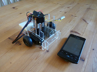
Simple, headphone-controlled phone robot

TL;DR: The headphone socket on some Android phones is a good enough signal generator to control servo motors almost directly.

I had an idea recently that servo motors could be driven directly from the headphone socket on an Android mobile phone. I was probably subconsciously remembering this old this old Hackaday link; anyway, it turns out that it's very easy to do.

Servo motors expect a square pulse of 5V of between 1 and 2 milliseconds, usually once every 20 milliseconds. 1 millisecond is canonically fully left, 2 is fully right, and 1.5ms is in the centre, although there is quite a lot of variation. So, I created a suitable square wave by hand in Audacity, saved it as a .WAV file and played it back on my phone's default media player app, while looking at the headphone levels on an oscilloscope. There are lots of reasons to not expect a square wave to come out of an audio amplifier, but the result was actually a very faithful reproduction of my square wave. The maximum voltage I could get out of it was just under one volt, not enough to drive a servo directly, but enough to turn a transistor on. On both the phones I've tried - a HTC Hero (G2) and Desire C - the voltage out of the headphone port is negative with respect to the value in the wave file, so the wave file needs to be between 0 (off) and -32768 (pulses) for a 16-bit sample. As well as playing back standard audio files, it's pretty easy to generate audio on the fly, so you can control servos direct from your application.

Here's my circuit diagram (I've only done shown one channel - it's identical for both). I'm not suggesting you try this - it might break your phone in some way I haven't thought of. This is just to show what I've done.


I've used two bog standard NPN transistors in my circuit; the second is acting as a second inverter as the first one inverts the signal once. I think it should be possible to do this with one transistor, and an inverted wave file (using 0 as the pulses and -32768 the remainder of the time) but it hasn't worked when I've tried it and I don't have ready access to an oscilloscope to figure out why.

Nonetheless, this is a very cheap way of controlling servos from a mobile phone and I would like to find out whether it works on more Android devices. The transistors cost about £5 for a hundred and there's just another 3 resistors per channel to make it work. It is limited to two servos, so if you want more connectivity, you'll probably be after more powerful devices like the IOIO.

This idea gets more useful when you use continuous rotation servos. Here's a video of my old phone running two such servos with wheels attached. Even old Android phones have cameras, accelerometers and wifi, which makes them great brains for simple robots. Running two servos from the headphone socket gives them very cheap mobility.

PS. I've since become aware of http://www.gluemotor.com/ which is a very similar device. They don't have any transistors; but use a capacitor on each channel to provide AC coupling. I couldn't get this to work when I tried it with my Android phone - maybe with more experimentation. Still, nice work.

Two more demos: Meteor Miner and Platformatic

Here's another couple of PyGame demos. Meteor Miner is a fairly straight clone of an old BBC Micro game, Thrust. Thrust was probably cloned from another platform, but it's not a style of game that has been used much recently. You control a spaceship by turning left or right and accelerating forwards, much like Asteroids, but the goal is to fly inside the structure of a meteor and recover ore. You can also shoot forwards to destroy the guns which will attack you inside the meteor.

Fuel is limited and ore makes you heavier. You can escape the meteor with just one tonne of ore, but the goal is to recover all of it.

This is the first game I've done with sound, although on all the platforms I've tried (Ubuntu, Windows 7 and Android) the sound suffers from an annoying latency. The game works well with the PyGame subset for Android but as PyGame doesn't handle multi-touch devices yet, I can't emulate the buttons on a touchscreen, so it will only be playable with a keyboard.

Platformatic is a puzzle game which looks like a platformer; rather than asking the player to time jumps exactly, it asks him or her to place instruction symbols onto the screen, which the character will follow when it treads on them. This partly came out of my frustration with platform games which require you to make a long sequence of carefully timed actions, often repeating the first ones hundreds of times until you finally get the last one correct.

I'm not particularly pleased with either of these games, but I've forced myself to bring them to a point at which I can publish them, as I otherwise tend to abandon old projects while half-finished and start on new ones.

Both games are available from my 2dgames repository on github and are MIT licenced: https://github.com/jmacarthur/2dgames. As before you'll need PyGame to play them; as I get better at creating games, I'll consider packaging some of them up or porting them so they can be played more easily.

Wednesday 18 July 2012

Investigating Raspberry Pi performance problems

I bought a Raspberry Pi some time ago and have been trying to run some of my PyGame games on it. I'm going to describe one performance issue I've seen with it. This isn't a criticism of the board in general, which I still think is excellent for the price.

I wanted to show something off at the Raspberry Jam last weekend in Cambridge, so shunted one of my games onto the SD card and started it up. The good news is that the Pi's standard distributions come with Python 2.7 and PyGame already installed, which saves a lot of time and effort. The bad news is that my game, previously running at 120+ frames per second on my desktop was down to 5 FPS on the Pi, which makes it unplayable.

Of course you wouldn't expect a 700MHz ARM1176 to be as quick as my Core i5, but this isn't a particularly taxing game, and I expected it to be well within the Raspberry Pi's capabilities. It's a 2D game, using lots of blits to draw tiled scenery, some bitmap rotates and vector arithmetic for collision detection.

My first suspect was floating point, as my game uses a fair amount to do polygon overlap calculations and I'm using PyGame's libraries to rotate bitmaps. The old Debian linux distribution for the Pi didn't use hardware floating point. Yesterday, the new new Raspbian image was released with hardware floating point support, so I gave that a try. No luck - it's still at about 5 FPS.

Python has a built-in profiler which can be invoked with
python -m cProfile myprog.py

It's best to sort samples by time and save this to a file, so I use:
python -m cProfile -s time myprog.py > profileoutput

(You can also use "-o file" to redirect the profile output to a file, but it's saved in a binary format if you do that, so it's easier to redirect stdout, although this does mix the profiler output with the output from your program)

Here's the profile from the Rasbperry Pi, with some information stripped out for brevity:

   225868   65.576 {method 'blit' of 'pygame.Surface' objects}
        1   47.159 thrust.py:1()
      605    3.082 {method 'fill' of 'pygame.Surface' objects}
      605    2.802 {pygame.display.flip}
    64433    1.967 {range}
    76268    1.741 {shipIntersectsBlock)
    10030    0.977 {pygame.draw.circle}


It's often useful to look at the profile on the well-performing case, so this is the profile from my desktop machine:

   748686   11.493 method 'blit' of 'pygame.Surface' objects}
        1    2.859 thrust.py:1()
     2321    2.523 {pygame.display.flip}
     2321    0.405 {method 'fill' of 'pygame.Surface' objects}
   499709    0.246 (shipIntersectsBlock)
   247663    0.081 {range}

Time at the file level of thrust.py has gone up proportionally on the Pi, but this is probably because the desktop version ran for longer and initialization code wasn't such a significant part. This wasn't a very carefully controlled test. The main thing to note is that 'blit' is what we're spending most of our time on, in most cases. 

To test this, I removed one blit from the code which blits the static background onto the screen every frame. As might be expected, the performance went up from 5.2 FPS to 8.8 FPS. That's small in absolute terms but a very significant chance proportionally.

Now, there's a number of ways to reduce that - the scenery doesn't change often, so it may be more efficient to construct a single scenery image and keep blitting this to the screen rather than blitting each tile individually, each frame. There's also a lot of settings to play with regarding pixel depth.

I've got a suspicion that one of the biggest problems is the resolution I'm running - 1824x1104, which is a lot of work for the graphics hardware. My game only runs at 640x480, but I haven't figured out how to get the Raspberry Pi's framebuffer to use a lower res - using a smaller monitor would be the easiest way, if I had one.

Update 19th July 2012: Tried this on an Android tablet (Asus TF300) and got 25FPS; and on a laptop with an Intel U4100 @1.3GHz; Radeon 4550 - 50 FPS. Both of these devices are quite capable of doing lots of 2D blits at 50FPS without breaking a sweat, so the culprit is likely to be a software problem.

Tuesday 3 July 2012

2D Platform games with PyGame

I've been writing computer games for quite a long time but rarely finish anything and never publish them. Just to show that I can actually finish things, here's Object Collector 2D, a tiny game very similar to Manic Miner and a hundred other old platform games. It took one day to program and comes in at 388 lines of Python while still, hopefully, being fairly readable in case any newcomers to Python or PyGame want to use it as an example. Don't expect a competitor to Braid.

I have a tendency to spend a lot of time working on the mechanics of games, finely tuning collision resolution and other rules. There's a great talk on YouTube by Martin Jonasson & Petri Purho called "Juice it or lose it" which shows how much more you need than good mechanics to make an enjoyable game, and it's these things I need to work on.

The code is in my github repository "2dgames", under the directory "collector": https://github.com/jmacarthur/2dgames/tree/master/collector. You'll need PyGame to run it.

Friday 8 June 2012

Exhibiting the Mk2 Turing machine

Here's a short video clip of the Mk2 Turing machine working at Derby Maker Faire. It took about 6 weeks from sending the plans off to RazorLab to having a working machine at the Handmade Digital exhibition in Manchester. There are still lots of handmade parts in the Turing machine, but having the majority of it laser-cut has made it much easier to construct.

There are also a lot of bugs in the design. One of the great things about the laser-cut design is that I can record these bugs as though they were software defects, which they are in many ways. The design for the machine is on github, at https://github.com/jmacarthur/millihertz/tree/master/scad/newbuild, although it may not be very intelligible at the moment. I really need to spend more time documenting the design.

Lots of people have said they like the shiny black laser-cut Turing machine, and others have said they prefer the scrappy style of the original. Personally I'd prefer to hand-make the final version out of solid brass, but that will be several iterations away.

Monday 12 March 2012

Automating layout of laser-cut models


On the left is a rendering of part of my revised Turing machine. The important feature of this, for this post, is that it's a 3D object made up of flat cuboids 3mm thick, which means its parts can be cut out of a sheet of 3mm material by a laser cutter. It's designed (or perhaps written) in OpenSCAD.

Turning this into a 2D drawing to feed into a laser cutter is a manual process at the moment. The best way I've found to do it so far is to comment out all but one top level object at a time, then add an OpenSCAD projection primitive; compile, then export the resulting object as a DXF. This needs to be done for each part, with potentially different projection settings for each, and then the DXFs need to be manually combined.


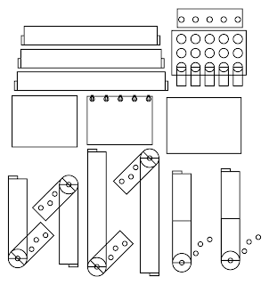
This next picture is a rasterized SVG which was produced by a perl script I wrote to do this job automatically. The only post processing I've done is to move the top level objects around, as they end up on top of each other at the moment, and to increase the line width. As you can see, this is not perfect, as there are more cut lines there than there should be, but it is automatic. Another advantage of this method is that the produced diagram has true circles in it, rather than the polygonal approximations OpenSCAD produces. The script won't work on objects that are not within a thin plane; the model shown was already split into those objects and had the tabs added by hand. This script is just doing the job of rearranging objects into 2D form.

I am hoping to get the Clipper library involved next to do 2D unions and intersections necessary to produce useful laser cutter drawings. This library can also do outsetting, which will be useful to correct for the diameter of the cutting beam. (Inkscape can do outsetting too, but there is a bug in the current implementation relating to small lines at right angles.) For example, the tabs on the end of the thin bars shown above should be part of the same object. The script knows that these are part of a union, so should be union'ed in 2D to remove the line separating them.

There are of course restrictions in what this can produce; it's limited to orthogonal cubes, cylinders and polygons. Anything that produces an edge not perpendicular to the plane of the object will not work, but then it couldn't be produced by a normal laser cutter anyway. It shouldn't be limited to orthogonal planes - any orientation should work, although I've not tried it with non-orthogonals yet.

This perl script runs from the processed CSG output from OpenSCAD. This is thankfully very easy to parse. I used Parse::RecDescent to parse it. Then there are several passes of tagging elements in the tree and determining which shapes are positives and which are subtracted from the original solid; then a lot of matrix maths to identify top level objects which all fit into a 3mm thick plane segment and to project all its components into the same 2d plane. I hammered out the perl script in one day, and it's full of bugs and very badly written, so I'm not going to publish it right now. If anyone is interested in it, I'll tidy it up and open source it.

Sunday 12 February 2012

Chorded keyboard for mobile phones


This is a chorded keyboard mounted around the edge of my mobile phone, a HTC Hero. Chorded keyboards have existed for ages and never really caught on, but I thought applied to a mobile phone it might be quite useful. I find existing keyboards for phones are a bit lacking; hardware ones are bulky and software ones are fiddly and take up screen space that could be better used. Chorded keyboards can potentially be more compact, and also have the advantage that they can be used without looking at them. It's currently -3 degrees centigrade in Cambridge, and I'd quite like to be able to control my phone without taking it and my hand out of my pockets while outdoors.


The keyboard is just five key switches connected to a IOIO board. To type a character, you hold down a combination of the buttons. The first button sends 'A', the second 'B' and holding down both then releasing gives you 'C', and so on. On a production keyboard, you would organise the most common letter to be the easiest key combinations. 'E', 'R', and 'T' would be single clicks, and 'Q' would require the least comfortable click combination.

There are 31 possible combinations of the 5 keys, which is room for the alphabet and a few extras such as space, backspace, shift lock and a couple of extra escape sequences to add numbers and symbols.

The IOIO board isn't ideal for this application, because it requires external power to operate rather than drawing power from the phone, hence the 9V battery. That and the bulky USB connectors make this impractical to use. I could replace the IOIO with another microcontroller capable of hosting USB if I wanted to make this a real device.

I also need to figure out how to write the necessary Android code to make this a general input method rather than just typing text into a custom application.

The case is 3d printed by Shapeways. It fits over the phone and replaces the normal back cover. There are spaces in it for the volume control, camera and headphone socket. The volume control could also be used as a 6th & 7th button for chording, if desired.

As it stands, the keyboard isn't particularly comfortable to use. The keyswitches require too much force and aren't in quite the right places yet. I think it's got potential though.